Select from the products you own. Watch for the ESD reminder shown at the left when removing printer parts. See your browser's documentation for specific instructions. For Windows NT 3. To accurately perform removal and replacement procedures or determine the correct part for reordering, you will need to know the version of the printer that is being serviced. The DIMM slots can be used to add memory, fonts, or firmware upgrades. 
| Uploader: | Kezuru |
| Date Added: | 6 October 2005 |
| File Size: | 35.84 Mb |
| Operating Systems: | Windows NT/2000/XP/2003/2003/7/8/10 MacOS 10/X |
| Downloads: | 60669 |
| Price: | Free* [*Free Regsitration Required] |
See the section in the online user guide on configuring input trays.
HP Customer Support - Software and Driver Downloads
Pre-troubleshooting checklist The list below describes basic questions to ask the customer to help you quickly define the problem s. The light passes through the cartridge when the toner around the detection port is scraped off by the cartridge stirring function and is detected by the light receiver of the toner level sensor PS1 2 see Figure LocalTalk network The LocalTalk interface enables you to print directly from a stand-alone Apple Macintosh computer or from a Macintosh computer on a LocalTalk network.
If necessary, insert a flatblade screwdriver between the shield and the frame to release the tab.

Please wait while we process your request. The DIMMs are then inserted into the available slots in the formatter board. This tool applies to Microsoft Windows PC's only.

The formatter sends the image data and the DC controller begins to create the image. Exposed areas can cause labels to peel off during drifer, which can cause printer jams.
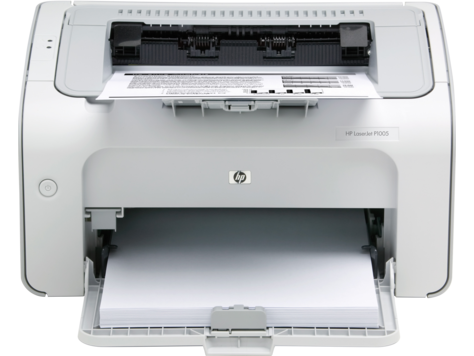
HP LaserJet P1005 Driver
Compare Configuration Pages to samples. See the instructions that follow to connect one or more network cables to the printer.
Laitteen saa avata ja huoltaa ainoastaan sen huoltamiseen koulutettu henkilo. The printer measures the time it takes for the toner to cover the port again so that light cannot pass through. Food and Drug Administration has implemented regulations for laser products manufactured since 1 August The printer's adaptive data compression had to resort to lossy compression to fit raster graphics in the available memory.
At this point, the printer stops printing and the drum cartridge must be replaced. drivee
Refer to the wiring diagram. This power is also used to supply power to the paper feeder. Avoid fanning the print media before loading it into the paper trays.
HP LaserJet P Printer drivers - Download
The pick-up motor M2 provides the drive force for the front of the paper path. Figure Developing PCB removal and replacement 1 of 2 6 Disconnect the connectors from the deiver PCB and release the cables from the metal cable stay callout 2, Figure on page Would you like to view the product details page for the new product? Below are recommendations for the printer location and placement. Removing it will affect printer operation. Once the separation roller separates the paper from any extra sheets of paper, paper is fed into the printer by the paper feeder feed roller and printer feed roller.
The image formation section of this chapter includes a description of this process and discusses operation of the motors and other items associated with the ITB. Synchronous SDRAM modules do not need to be configured drkver pairs in corresponding left and right slots.
To remove the toner catch tray, pull downward on the tab and slide the tray out of the rear of the printer.
To use the enhanced capabilities of the bidirectional parallel interface such as bidirectional communication between the computer and printer, faster transfer of data, and automatic configuration of printer drivers, your software application must support these capabilities. Any residual toner left on the ITB is charged positively for removal.
As the developer sleeve and drum rotate past one another, the toner particles are drawn to the drum's surface. This process uses upper and lower rollers made of Teflon tubing to reduce sticking. Converting the voltage on the printer can damage the printer. Place the printer in diagnostic mode and run the drum test to verify drive spindle movement for both the imaging drum and ITB.

Комментариев нет:
Отправить комментарий